
flow diagram on processing of coal manufacturer Grasping strong production capability, advanced research strength and excellent service, Shanghai flow diagram on processing of coal supplier create the value and bring values to all of customers.
 WhatsApp)
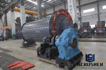
A flow diagram is a diagram representing some kind of flow. ... Process flow diagrams. A process flow diagram (PFD) is a diagram commonly used in chemical and process engineering to indicate the general flow of plant processes and equipment. ... Water cycles of a coal fired power station Electrical energy distribution in a coal fired power ...
Figure 1: A Simplified CoaltoSNG Block Flow Diagram. The economic viability of producing synthetic natural gas (SNG) through coal gasification is heavily dependent on the market prices of natural gas and the coal feedstock to be used, in addition to the capital cost of the gasification plant. ... SNG from Coal: Process Commercialization.
How a Coal Plant Works. ... condensed back into water and returned to the boiler to start the process over. Here''s a reallife example: The Kingston Fossil Plant near Knoxville, Tenn., burns coal to heat its boilers to about 1,000 degrees Fahrenheit to create highpressure steam. The steam is piped to the turbines at pressures of more than ...
Coal Mining Process Flow Chart Diagram Coal Processing Diagram # – Coal Mining Flow Chart, with 37 More files. Coal Mining Process Flow Chart Diagram Coal Processing Diagram # – Coal Mining Flow Chart, with 37 More files. Free Flowchart Templates
A process flow diagram for a typical coal cleaning plant is. Chat Now. Hydrogen Production from Fossil Fuels eolss. are detailed including process flow diagrams. A brief review of the efficiency ... Following natural gas and oil is the process of steam gasification of coal. In these.
2. Basic Schema of the Rectisol® Process ¾Block Flow Diagram and Simplified Process Flow Diagram ¾Achievable Product Quality of the Rectisol® Process 3. Polygeneration Concepts with the Rectisol® Process ¾Multi Products with one Acid Gas Removal System 4. CO2 Emissions Clean Energy ¾CO2 Capture with the Rectisol® Process 5.
This flowchart made of machinery icons explains or expresses in simple but clear terms the step of the Copper Mining and Copper Extraction Process. Starting from either openpit or underground mining and using a different relevant treatment method for oxide or sulphide copper mineral (ore). Having a quick look now at how porphyry ores are treated and the metals extracted.
Typical Process Flow Diagram of IGCC plant EnggCyclopedia. As shown in the process flow diagram, the coal is first slurried with water and fed to the first stage of the gasifier Oxygen with a purity of 95% is provided from .
Coal based power plant SlideShare. Jun 16, 2014 Steam Flow DiagramSteam Flow Diagram 9. Coal to ElectricityCoal to Electricity 10. • A coal handling plant is the area of the thermal power plant where the raw coal is brought from the coal mines and is processed into a form that can fed into the boiler.
Flow diagram of coal to coaltarpitch process (Public domain.) Thumbnail Medium Original. Detailed Description. Coal tar is a byproduct of the coking, liquefaction, or gasification of coal. Coaltar pitch is the residue that remains after the distillation of coal tar. Coal tar and coaltar pitch are used in coaltarbased sealcoat products ...
As shown in the process flow diagram, the coal is first slurried with water and fed to the first stage of the gasifier. Oxygen with a purity of 95% is provided from the Air Separation Unit (ASU) and the coal is partially combusted to maintain a temperature of 1370 °C.
coalfired power plant. This process flow diagram illustrates the three turbine groups (high, intermediate and low pressure turbine), the condenser, the feed water tank, the four low pressure and two high pressure preheaters and the subcomponents of the steam generator. The steam generator, as exemplarily shown
Sep 03, 2013· The purposed operation of this plant is to improve the mine product recovery by collecting roof floor materials as wash feed, which usually dump as waste. This is a part of coal .
A process flow diagram (PFD) is a diagram commonly used in chemical and process engineering to indicate the general flow of plant processes and equipment. The PFD displays the relationship between major equipment of a plant facility and does not show minor details such as piping details and designations. Another commonly used term for a PFD is a flowsheet
Coal The fossil fuel used in the combustion process for White Rose Dense Phase Fluid state that has a viscosity close to a gas while having a density closer to a ... Process Flow Diagram Process Flow Diagram (PFD) is a drawing which describesthe process flow for a processing plant. PFD is used to capture the main process equipment
crushing and screening process flow diagram; steel mill production process flow diagram; natural rubber process flow diagram; aluminium rolling mill process flow chart; crusher equipment flow chart; flow chart iron ore export; iron and steel making flow chart; coal processing flow chart coking coal; sand mining process flow chart silica ...
Mining and mineral processing Everything Science In ancient times mining and mineral processing were very primitive and the main method used to extract ores was ...Coal miners used to take a canary with them down the mines. ....Figure 2: Flow diagram showing how gold is processed.
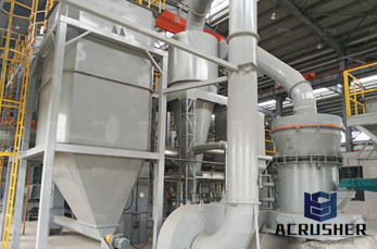
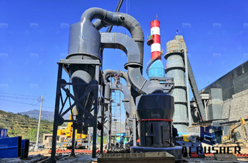
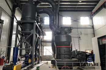
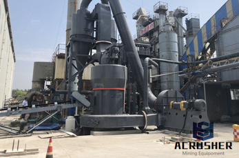
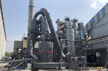
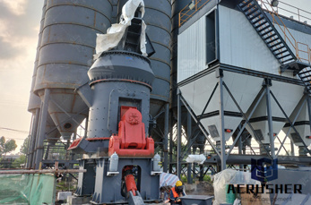
Coal processing has two forms, here descripe flow chart of coal processing plant: Industrial process is the coal after the coal crusher, with the belt conveyor to quantitative feeder, to pressure the ball machine feeding by quantitative feeder uniform, sometimes need to improve the coal briquette strength, therefore, quantitative feeder and intermediate pressure ball machine can also add ...
Recommendation: There should be renewed support for advanced coal mining and processing research and development to optimize use of the nation''s coal resources by increasing the amount of coal that is economically minable through technological advances that .
Oxyfuel Coal Combustion Power Plant System Optimization. This airfired power plant releases 350 tCO2/hr. Figure 1 shows the process flow diagram for both the airfired...Current conventional coalfired boiler plants burn coal...
flow diagram for coal processing . The flow diagram and description in this section are based on a delayed coking unit with a single pair of coke drums and one feedstock furnace. However, as mentioned above, larger units may have as many as 4 pairs of drums (8 drums in total) as well as a furnace for each pair of coke drums. Contact Supplier
Figure 1 shows a simplified block flow diagram (BFD) of a methanol (MeOH) plant based on coal feedstock. Syngas from the gasifier is cooled by generating high pressure (HP) steam in the high temperature (HT) gas cooling system before being water quenched and scrubbed to remove fine particulates. The scrubbed syngas then goes through a sour water gas shift (WGS) to adjust the H2to .
Multotec''s Coal Industry Flow Sheet. We use cookies to improve your experience on our website. By using our site you agree to Cookies Policy
Figure illustrates the major process equipment in a schematic diagram of a byproduct coke oven battery. Flow diagrams are provided in Figures and 3 to give an overview of the process from coal preparation to byproduct recovery. These operations will be discussed in greater detail for the
WhatsApp)